Introduction
One of the functions often desired for a layout that has a CTC panel
is some simple way to lock and unlock local turnout controls from the
CTC panel. The most direct way to accomplish this is to enable/disable
the 'Common' side of the switch providing local control.
Background
Prototype CTC panels often had the capability to lock and unlock the
remote turnout mechanisms in order to allow local crews to change
switch positions manually without constantly calling in to the
dispatcher for changes in routing. There are various ways that modelers
have chosen to simulate that function, including the issue of 'keys' to
operators.
How It Works
The TC-64 uses different ports for inputs and outputs. These ports may be configured to send and respond to the same commands. I.e. an input port may generate turnout commands in response to contact closures. A second port may be addressed the same and respond to those commands by driving a turnout motor. TC-64 inputs require a contact closure to ground. If we use an output of the TC-64 to provide that 'ground' to the local contact we can enable or disable it remotely from the CTC panel.
Problems
The primary difficulty with this solution is to get the panel images
correct to represent the 'lock' lever and indicators.
Advantages
The advantage of using the TC-64 for this operation is that it
always sends the 'local' turnout commands on the LocoNet so that the
CTC panel always shows the current position of the turnout, even
without the extra expense of feedback contacts. Using a push button
switch allows the use of multiple buttons at different locations. If
the operator can not see the turnout position, and no use is made of
turnout position indicators, then dual push buttons or a SPDT switch
may be used.
The LED lamp is a visual aid to the local operator to show him when
he has local control of his turnout.
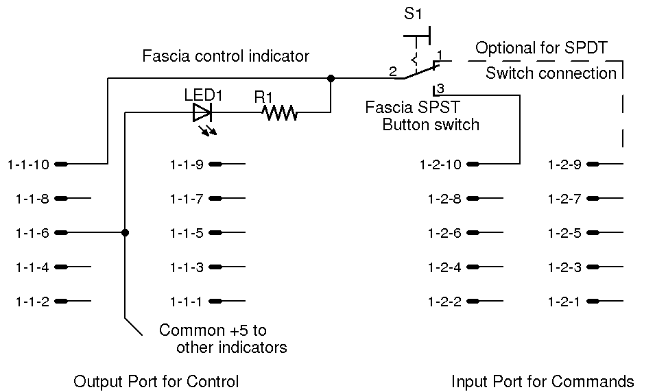
The Wiring
Set the output (control) port to Type 'Driver'. Set the input (command) port to be 'Alt Button'.
Connect the LED indicators and local control buttons as shown below.
Each button press of S1 will send alternate 'Thrown' and 'Closed'
commands from the Input line at 1-2-10 as long as the Output line at
1-1-10 is low. If the Output line at 1-1-10 is high, then there will be
no commands sent on button is presses.
Modifications
One modification is to use a SPDT local control toggle switch
instead of a single push button. To do this wire the NC side of a
double throw switch to the next input line so the SPDT switches are
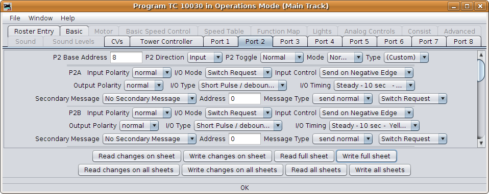
wired to pairs of inputs. The Input port configuration must be changed
to be the custom setup as shown below. Note especially: Direction,
Toggle, and Mode, for the port. Also Input Polarity, I/O Mode, and
Input Control, for each individual line. (click to enlarge image)
The Parts
LED1 Indicator LED
R1 330 ohm
S1 button switch