Applications Notes (Nov '06)

Signal and Indicator wiring:
One of the best descriptions of CTC signaling from both a modelers and prototype perspective that I am aware of may be found at the Control Train Components web site. There are several different options for wiring up signals and panel indicators for your model railroad. Normally these signals and indicators will use LEDs for illumination. We may cover options for incandescent lighted signals at a future time. The two primary options are to drive the LEDs directly from the Tower Controller outputs, and to use a driver card such as the 4ASD-4. Obviously the least cost option is to drive the LEDs directly as that saves the cost of an extra board. However, in some cases the extra board is justified or even required.

Signal arm or signal head = Each individual signal unit
Aspect = The speed or route indication given by one or more signal heads or arms.
Marker = A signal head or arm that does not change color or position.
Light = The individual lamp in a signal. A light may indicate multiple aspects if it changes color like a searchlight signal, or it may take multiple lights to indicate a single aspect, for example in position light signals.
Mast = The pole that mounts one or more signal arms that (usually) control each individual track.

Single connectors are shown in these schematic drawings, but normally each signal mast will have its own connector spaced out along a single ribbon cable coming from each port or driver card.

Direct drive options:

Searchlight Signals
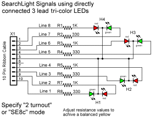
The simplest and most cost efficient option for signals is to use three wire dual color LEDs to create searchlight style signals. The three wire LED design allows both the red and the green portion of the LED to be illuminated independently. If the LED has both color chips located close to each other and the brilliance of the two colors are well matched then our eyes will see yellow when they are both illuminated at the same time. This visual multiplexing allows us to drive 4 heads, each with 3 aspects plus dark, from each output port.

2 wire bi-polar LEDs have also been used, but their operation is more complex because their polarity needs to be reversed to change from red to green and their polarity must be rapidly switched with a variable pulse width to achieve a proper yellow. Further there is only a saving of one wire, the common return, over the use of three lead LEDs.

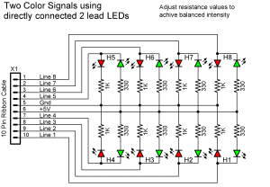
Two Color Signals
Direct drive of dual LEDs is possible for users with simple two color signals. In this case 8 dual color signals may be controlled directly from each output port. The color changes from red to green as the output lines change between high and low. LEDs must be individual LEDs, contrary to the first schematic I posted which also showed using bi polar LEDs. (updated 28 Sept, 06)

Panel Indicators
Panel indicators will usually be directly driven from the outputs of a Tower Controller located behind the panel. For dual color indicators use the same wiring shown here for the direct drive two color signals. To drive single color LEDs just use single resistors and single LEDs. For three color panel indicators use the same circuits that are used for line side signals.


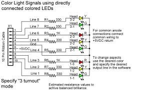
Color Light Signals
Color light signals of various styles may also be directly driven from the outputs of a Tower Controller. However there is some loss of efficiency because it takes three or four lines to directly drive these same signals. (three or four aspects may be encoded using just two lines) Also the usual three aspect signals do not map well onto the 8 line ports, yielding only 2-2/3 heads per output port. This means that connections to one head may span two ports. Another disadvantage to this method is that it takes 1 wire per light from the TC-64 out to the signal heads. There is no opportunity for multiplexing the lines to cut down on the total amount of wiring required. On large layouts the extra wiring cost alone can justify the use of driver cards.


Driver board options:

All the following circuits may be built as either common anode or common cathode versions. Simply switch the polarity selector on the driver board to match. Common anode versions are shown. To wire common cathode versions just reverse the direction of each LED.

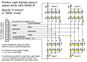
Position Light Signals
Position light signals are more difficult to drive than color light signals due to the number of LEDs involved. The simplest wiring option is shown here. However this connection puts three yellow LEDs in series for each aspect. Yellow LEDs require over 2 volts each to illuminate, so it is not possible to drive this simply wired head directly from a 5 volt source. To solve this problem the 4ASD-4 board includes a voltage mirror circuit that supplies approximately 9 volts to the driver circuits. This board also multiplexes the output lines and includes the current limiters internally. This allows 4 heads to each be driven with 4 aspects using just 10 wires. Normally we drive 4 heads, with just 3 aspects each plus dark, on each output port. This frees the 4th aspect connections to optionally be used to illuminate fixed marker lights if so desired.

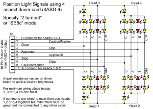
Absolute Position Light Signals
For the late era use of red lamps as an Absolute Stop indication in some position light signals use the alternate wiring as shown. These were apparently modified from existing signals by simply changing out the lenses in the stop aspect and were wired to not illuminate the center lamp when stop was active.


Color Position Light Signals
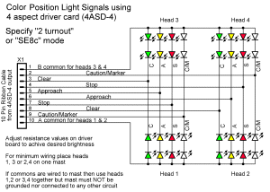
Color position light signals only require 2 LEDs in series, so they may be directly driven from the outputs of a Tower Controller. However this can be problematic using logic level outputs because of the required voltages to illuminate series LEDs properly. To avoid potential problems with dim indications, this schematic shows them being driven with a 4ASD-4 driver card. The 4ASD-4 can drive them easily and also saves on the amount of wiring required. Color Position Lights were often used in conjunction with additional marker lights for speed indications. If your situation requires a single fixed marker indication and does not also require the lunar aspect, then it may be lighted using the marker option.

Color Light Signals
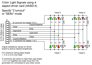
As noted above, color light signals may easily be driven directly from the outputs of a Tower Controller. This schematic shows them being driven with a 4ASD-4 driver card to save on the amount of wiring required and number of ports used. Color Light Signals are often used in conjunction with additional marker lights to indicate absolute signals. If your situation requires a single fixed marker indication and does not also require the lunar aspect, then it may be lighted using the marker option.


Last updated  Sept 26, '06
Copyright © 2006 Dick Bronson