First break the boards into individual units, and smooth out any rough edges that result with a file or sanding board.
First place the board on a hard flat surface with the components facing up.
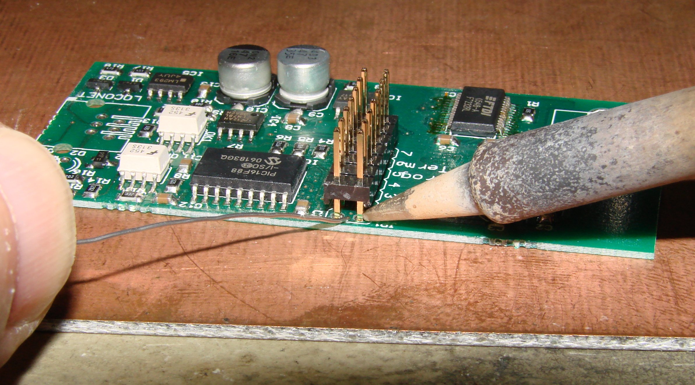
Next insert the header making sure that it is square and sitting on the same surface as the board.
Note that we use the entire uncut length of the header pins.
Next tack solder one pin of the header to keep it in position.
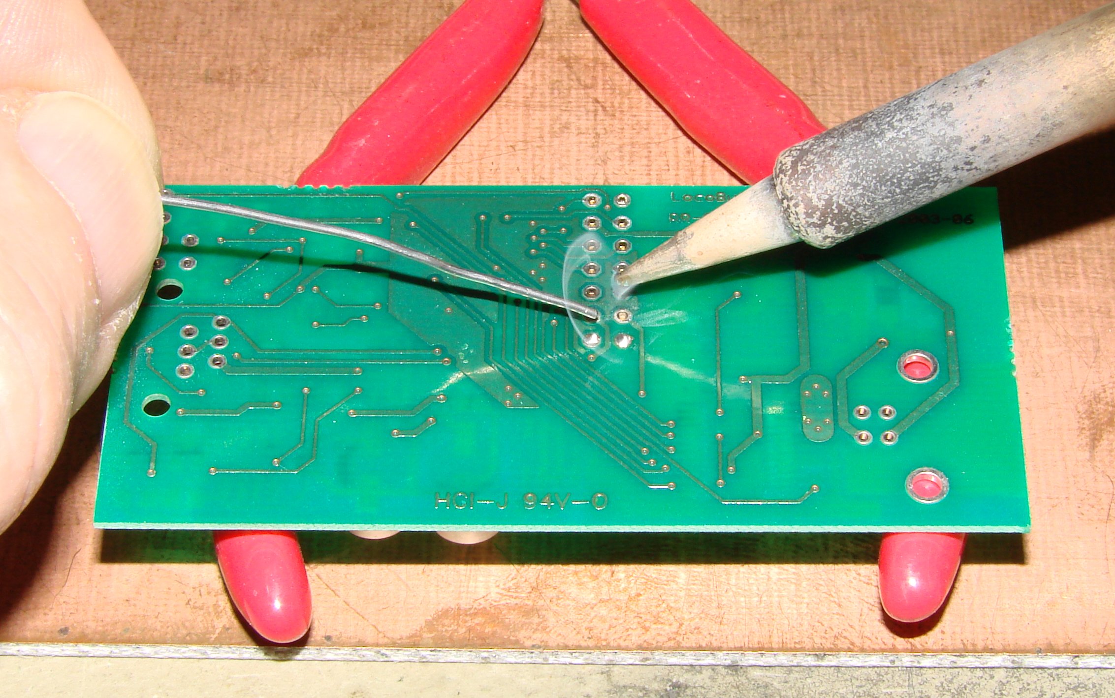
Now flip the board over and support it so there is no strain on the header and solder all the points. Start opposite the pin that has been tack soldered. Note that all the pins should be exactly even with the surface of the PC board.
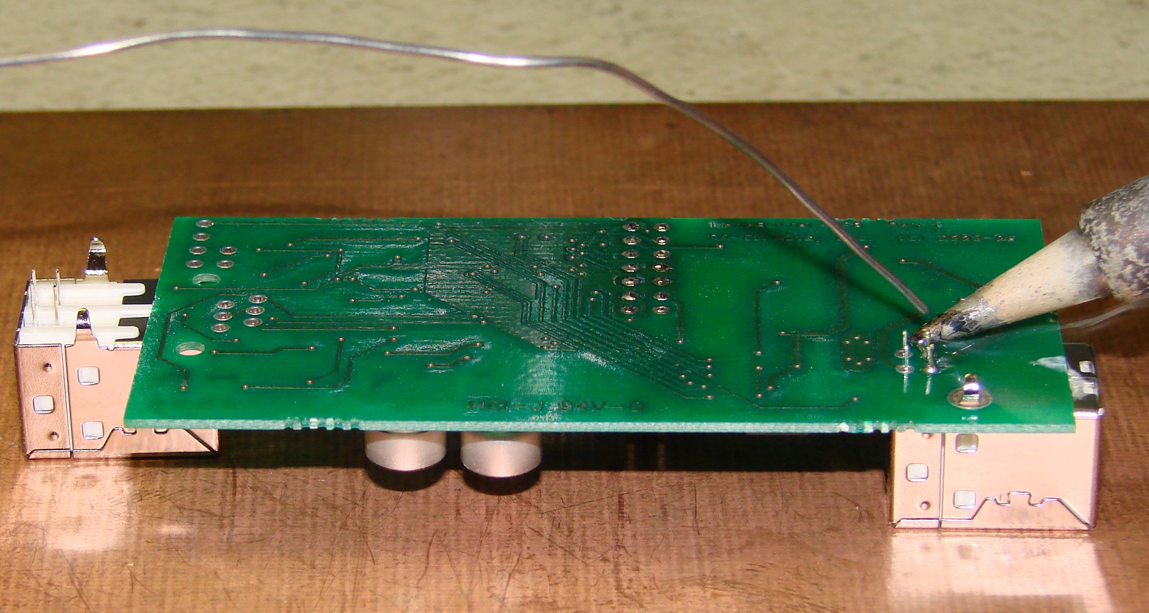
I use a spare connector to prop the board up to a level position which lets the USB connector sit flat for soldering. Solder one or two of the leads, then check that the connector is square with the board. Some connectors fit loosly in the mounting holes, and will twist out of position easily. Trim these leads flush with the bottom surface of the PCB when done.
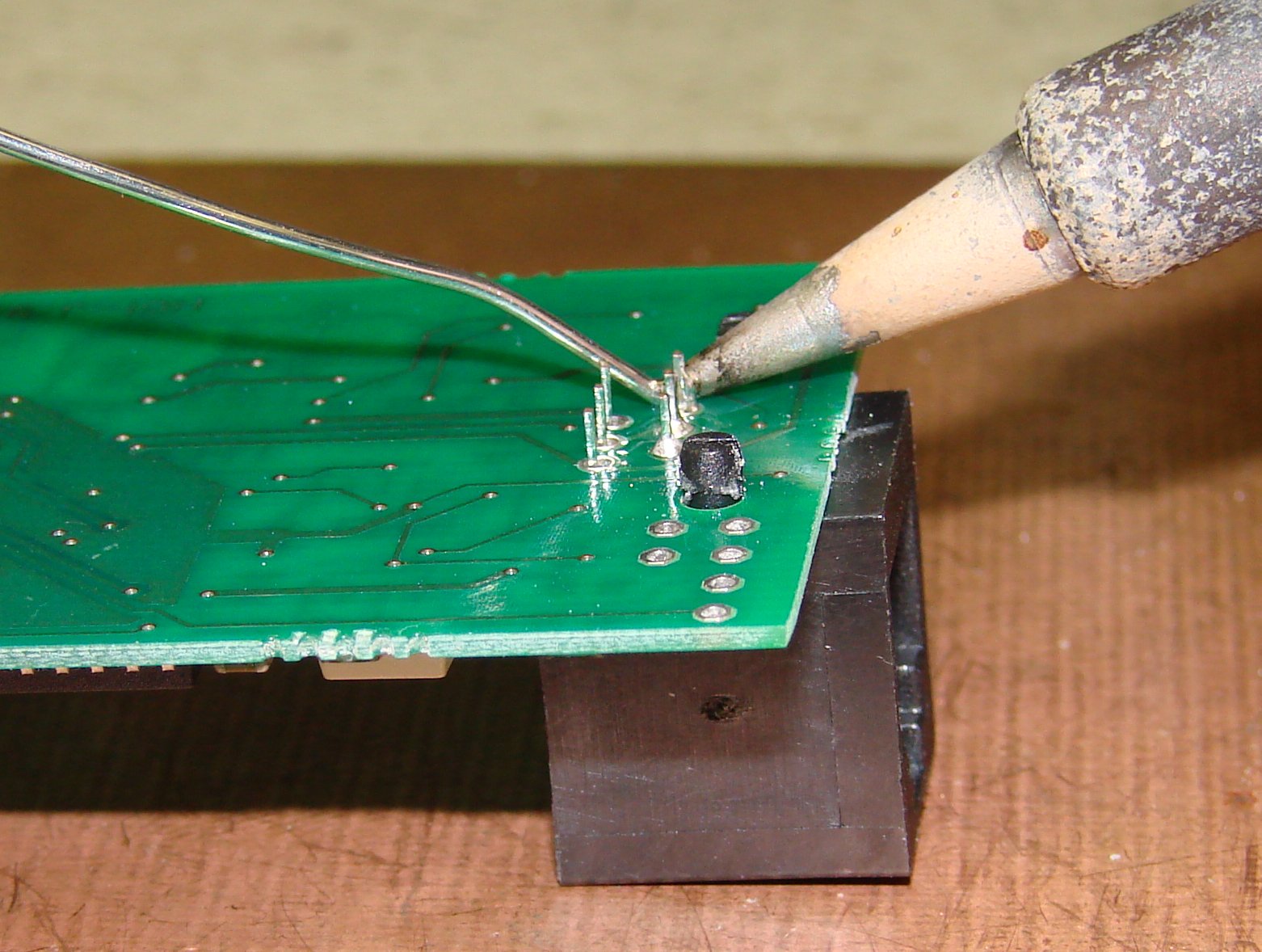
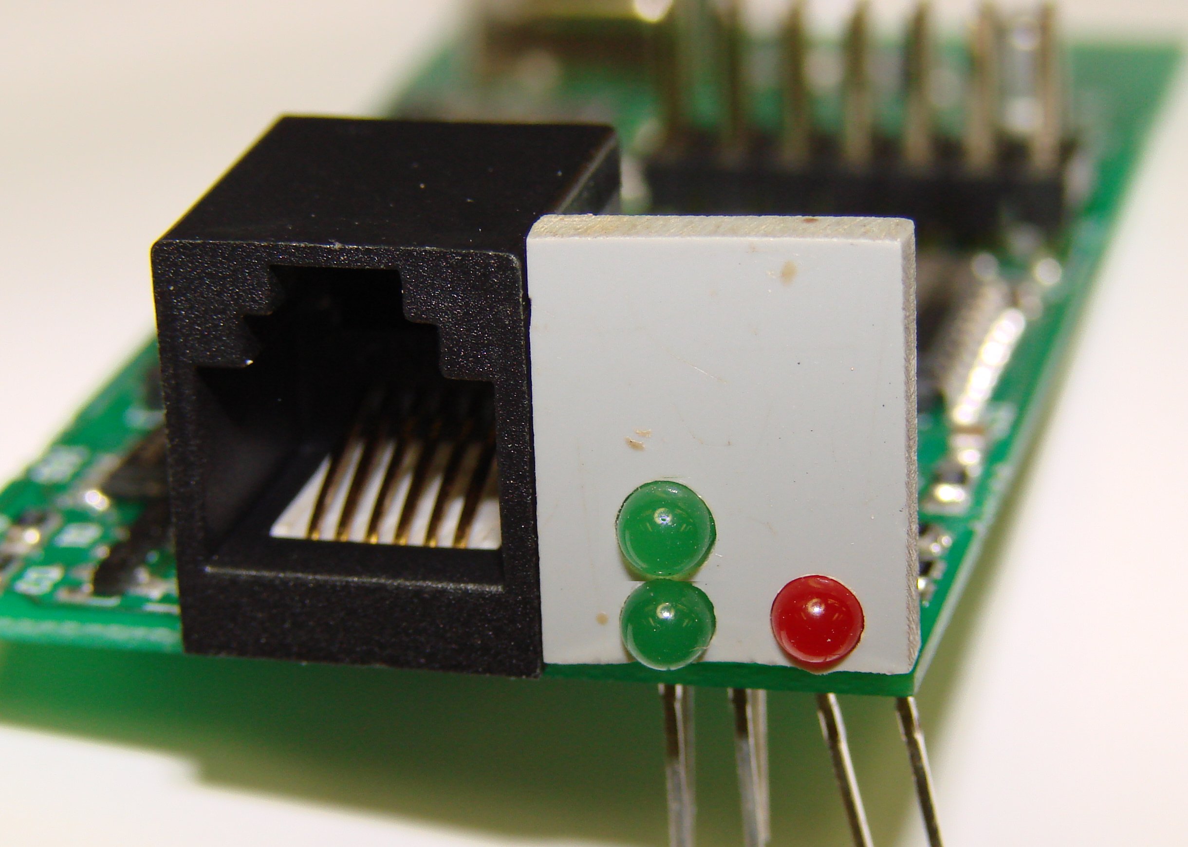
Snap the modular jack into place and be sure that it is seated properly down onto the PC board. This is important because the jack mounting studs are designed for 1/16" board thickness and do not retain the jack properly on these 1/32" thin boards. Trim the leads close to the board, but leave the mounting studs. Later we will melt down the studs to secure the jack in place.
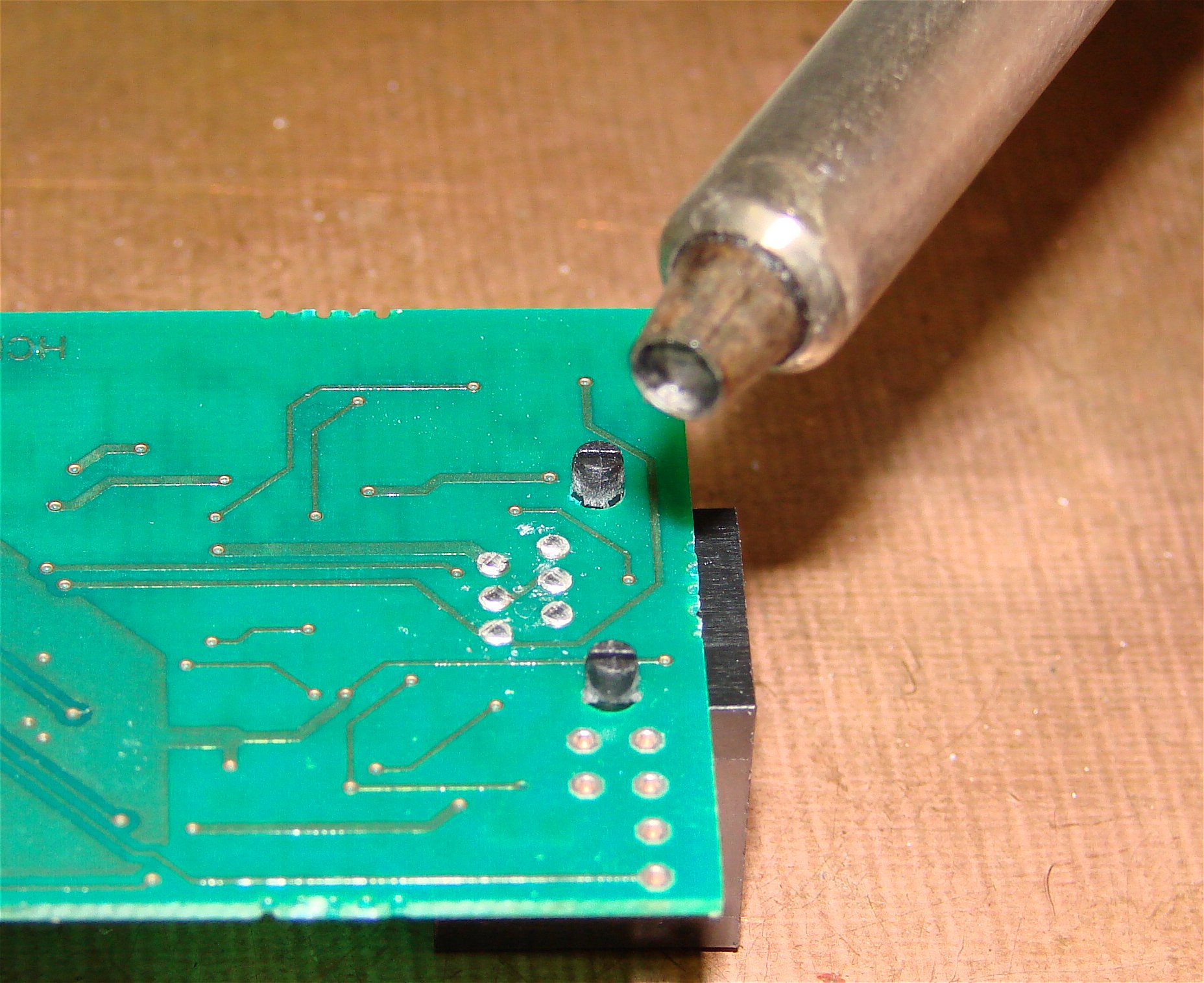
To melt the mounting lugs I made a special soldering iron tip. The hollow point is 3.4mm in diameter and 0.8mm deep.
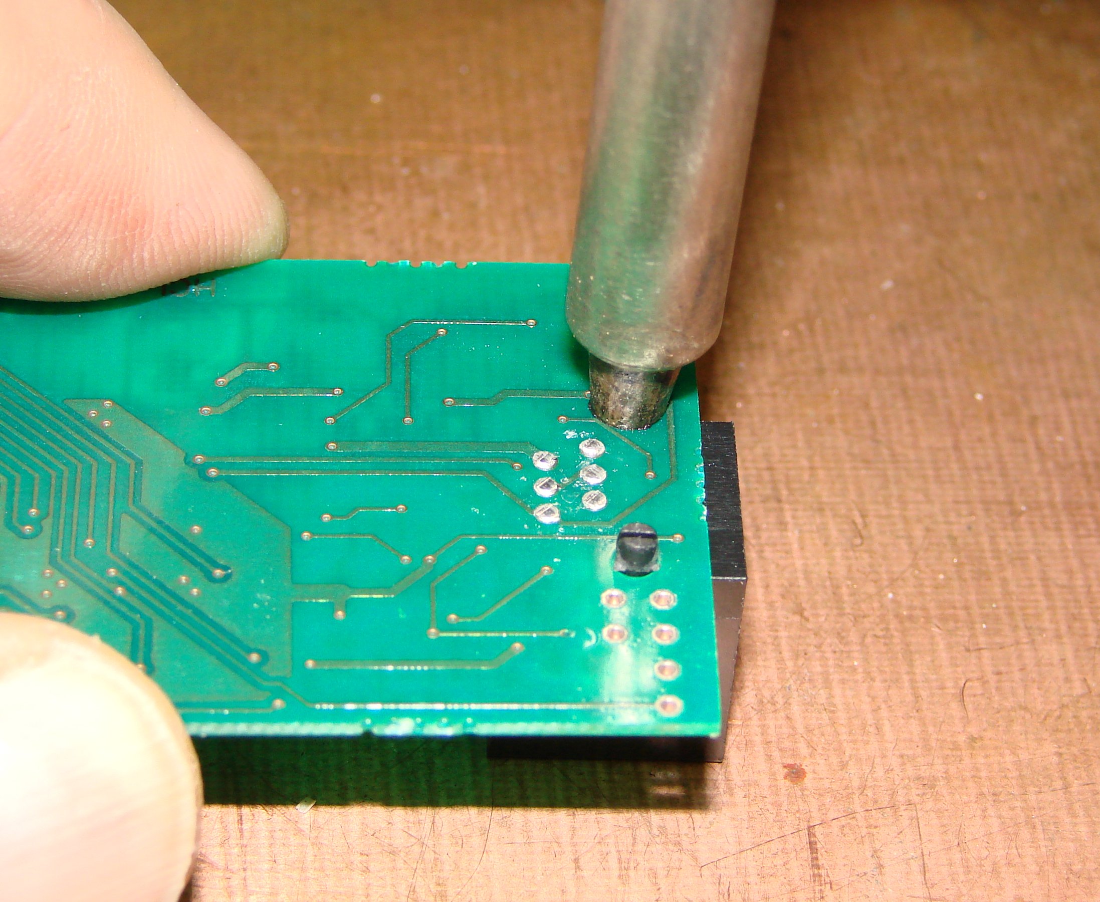
We set the tip temperature to about 270°C and use it to form the lug so that is is not over 0.8mm high. This step takes 3-4 sec. When you remove the hot tip there will be some plastic strings and a rough surface. I immediately (less than 1 second) quickly tap the hot plastic with the tip of my finger.
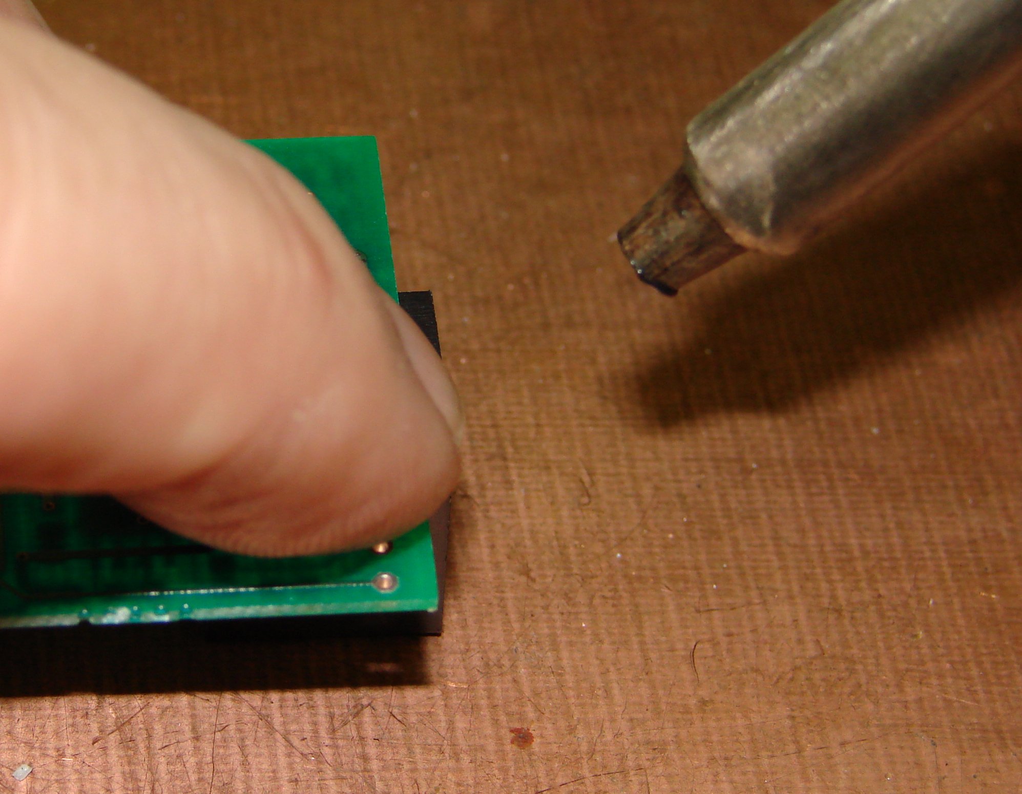
Very quickly tap the hot plastic lug to smooth it nicely.
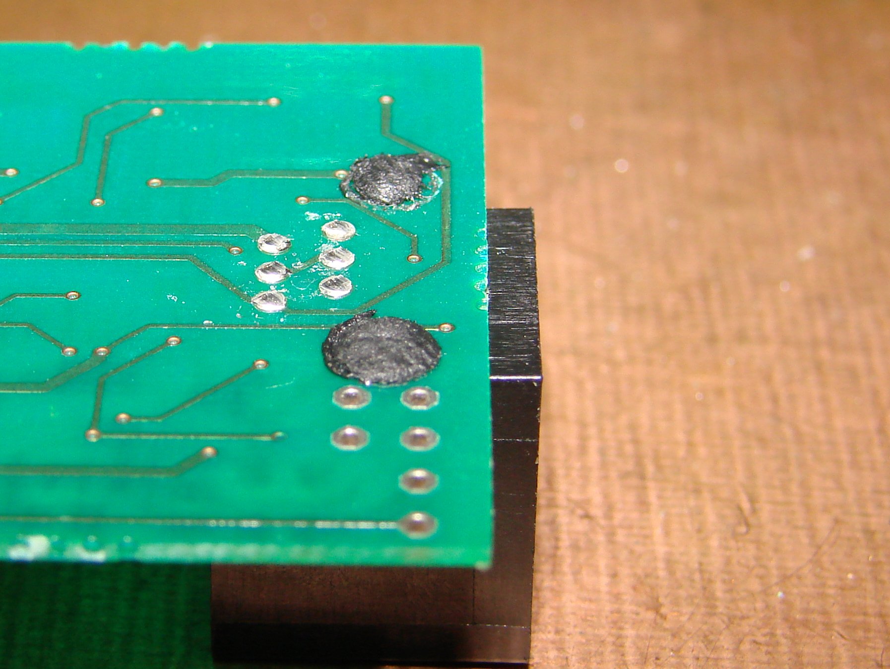
The result is a smoothly rounded lug that securely holds the modular jack to the PC board, but does not stick high above the surface and interfere with the case.
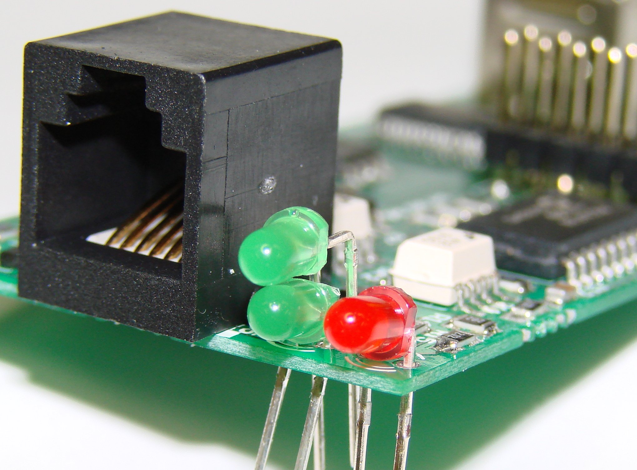
The three LEDs have their leads bent at 90° to fit into the case. The two lower LEDs have their leads bent close to the LED. The upper LED has its leads bent further out. Note: the two green LEDs have their flanges nipped off so that they can sit next to each other. This is necessary in order for the LEDs to fit into the lower part of the case. (below the case parting line)
Using a scrap piece of plastic with holes drilled at the proper spacing, align the LEDs and hold them in place for soldering.
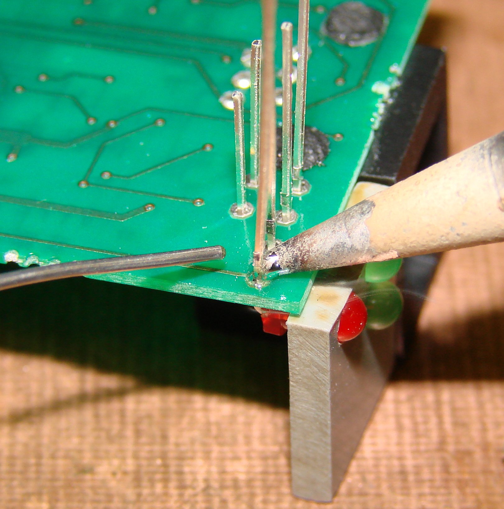
The plastic alignment block is the same height as the modular jack, so it sits on the plate and holds the LEDs close to the PCB and properly aligned for soldering. After the LEDs are soldered, clip all the LED leads close to the board. This completes the assembly of the board. Clean off any flux residue from the reflow and manual soldering. Once the boards are clean and dry they are ready for programming.