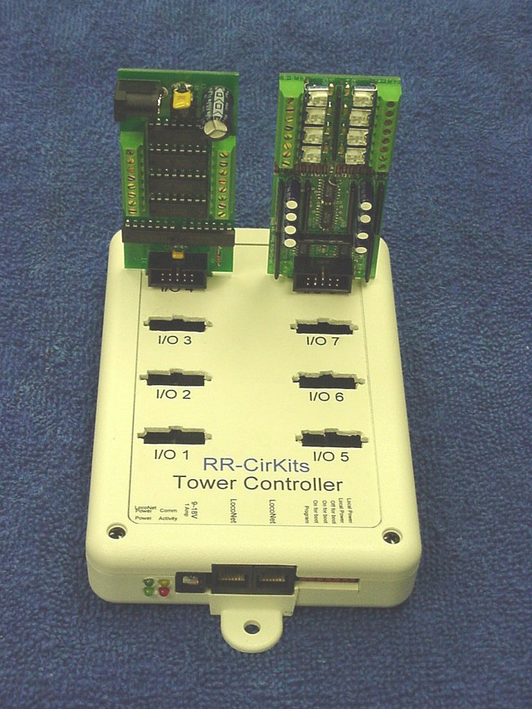
Prototype of the new
RR-CirKits 64 line Tower Controller.
(Prototype units pictured) Shown with Octal "H" bridge
driver and original version of the 8 block CT (current transformer)
occupancy detector daughter cards. Daughter cards may be
plugged directly into the Tower Controller or for those with limited
space or difficult mounting situations, they may be mounted remotely
and connected to the Tower Controller with a standard 10 pin flat cable.
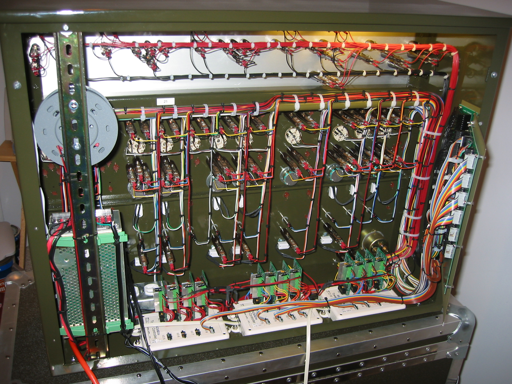
This installation uses 12 "H" bridge drivers in single ended mode to drive the ninety two 24 volt lamps, meter, and bell. All switch and lever inputs simply connect to ports configured to be Tower Controller inputs. Mike chose the "H" bridge driver boards for their relatively high voltage and current drive capability. The large board to the right was created by Mike as a termination point for his harness and conversion to the ribbon cables connecting to the Tower Controller inputs. (click on image for a larger version)
The RR-CirKits Tower Controller is designed to make multiple functions of your choice available at each major junction, passing siding, or control panel on your layout. This can reduce the wiring complexity and cost of adding signals, occupancy detection, turnout control, push buttons, LED's, and many other animation functions associated with each location on your layout. Each of the 8 ports supports 8 lines of input or output data, plus the 5V power required by most of the various daughter cards. Dual coil and DC turnout driver ("H" bridge) daughter cards will require separate isolated power supplies. (or common ground with the Tower Controller)
Updated CV info. New options for 64 line Rev-d board.
Some planning sheets to help setup the TC. Initial setup. Basic Info. DecoderPro XML file for programming.
Current status: Firmware in development. First hardware prototypes for the 64 line version are available.
Tower Controller Board Rev-d
Tower Controller wiring diagram (Dec 6 '05) 64 line Schematic (updated 16 May '05) 64 line Parts (updated 16 May '05) 64 line SV values (updated 15 Dec '05)
This new board is designed to be compatible with the LocoNet control bus (not yet LocoNet certified) and includes the following features.
Uses a PIC18F2525 running at 20Mhz for ample stored SV capacity. One controller for multiple functions allows a low cost per line. Replaces 8255 boards in many RR-CirKits applications. LocoNet (not yet certified) inputs are opto isolated to prevent power supply ground loop problems. On board termination for all I/O pins. (4.7K pull ups) 64 lines of Input/Output. Direction is an SV controlled option in 8 line groups. Each 8 line group is connected to it's own 10 pin RR-CirKits standard connector. Input from BOD, switch contacts, etc. Drive DDB, LED's, etc. Cool running internal 1 Amp switching power supply (8 - 35 VDC or 6 - 24 VAC input) powers the controller plus most daughter cards. Serial port Boot Loader Programming option for experimenters and upgrades. Individually buffered outputs allow for full 15 ma. load on all output lines simultaneously. Each 8 line port has it's own SV stored starting address. Master reset option for all SV's except port addresses. Option to store all output states during power down. (Prevents switch machines and signals from throwing randomly on power up.) Optional Ops Mode programming. Paged mode programming without connecting to the programming track. DecoderPro support planned. Each line has it's own SV programmable input or output features. Input: Transition state and polarity. Output: Steady, Pulse, Blink, and Invert of all. Each input or output line transition may optionally output a secondary (cascade or slave) command to any DCC address. (two SV's per line, command + address) This option allows for many interesting options such as single button ladder routing and master/slave control panels. Linux, PC and Mac software available from JMRI to calculate SV values and send programming commands. Read back of SV values in Ops Mode or Service Mode.