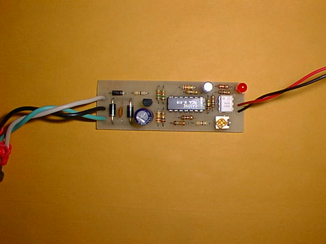
Link to picture of original
Detector. (52KB)
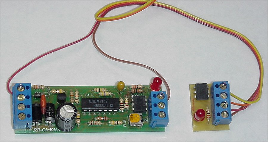
Link to picture
of Rev-H Detector and expansion module IB-A. (93KB)
Low cost dictated the use of readily available inexpensive parts, not
necessarily the fewest parts. The simplest way to get a voltage drop for
detection is to add one or more series diodes in the track circuit. However
each diode cuts the available voltage by about 5%, so the fewer the better.
The nature of DCC requires the sensing of both polarities for reliable
operation. (especially during analogue operation) The availability of track
power at all times led me to choose to power the sensor circuitry from
the DCC track power itself. The current drain of this circuit is very low
(3-4ma) when the track is not occupied, and only increases to about 10ma
when occupied, so the power drain on a booster is not noticeable.
D1-D2 provide a voltage drop to detect. C1 acts to cancel out the effects of track capacitance at the DCC switching frequencies, and improves the stability of the circuit when you are running non decoder equipped engines in analogue mode. Early versions of this schematic called for a value of .01 mfd for C1. Experience has shown that a value of .033 mfd works better in conditions where there may be any more than normal amounts of stray capacity in the rails and feeders. If your D1 and D2 are large sized, it may be easier to mount them vertically to improve the clearances to C1 and C2.
D3, C2, and the 5 volt regulator VR1 provide DC power for the circuit. R1 is to limit the peak charging current of the power circuit and also acts as a fuse if the circuit fails.
R2, R3, and R15 act as an input voltage divider and biasing circuit. R4 is to limit the current in R15 if it is adjusted to it's minimum position. R5 and R6 generate a positive reference voltage, and power bus 'B' serves as the zero reference point. R15 controls the amount of current required to reach the reference voltage points. The circuit is designed to respond to 10K ohm wheel sets, so the adjustment range is from about 50K ohm at maximum sensitivity to about 4Kohm at a minimum across the rails. U1-A senses the negative transitions, and U1-B senses the positive transitions of the DCC signal.
If you do not need to adjust for special conditions you may replace R3 (10K) with a value of 15K ohms, and replace R4 (47 ohms) with a value of 4.7K ohms. Omit the variable resistor R15, and replace it with two jumpers connecting all of it's original connection pads.
Noise from dirty wheels is always present, especially if only one or two wheel sets are in a block. C3, R7, R8, and R9 are the timing circuit. The timing may be varied by changing the value of C3.
U1-C drives the output stage. R10 and R11 provide a bias point for the
driver, while R12 and R13 provide the hysteresis necessary for stable switching
action. R14 is the current limiter for LED 1 and the opto isolator. If
you need to drive more current in the output of the isolator you may vary
the value of R13. I use 4N28 isolators because they are the least expensive,
but many different opto
isolators will serve as well depending on your needs. If you are using
simple open collector switching into a logic board like I am, be sure to
check that your isolator has enough gain to drive the pull-up resisters
used on your board.
Link to PC layout
Rev-G (11KB) (Updated 29-January-99) (reference
only, no longer available)
Link to PC layout Rev-H
(12KB) (Updated 5-February-01)
This version of the PCB Layout is functionally identical to Rev F, with the exception that I have changed the circuit to have an inverted version of the output signal available on pin 3 of the opto isolator socket. (which is unused by the opto isolator itself) There is also the option to attach a common solder cup style DB-9 connector at the power end of the board. Simply slip the board between the two rows of pins with the 5 pin row on the solder side. Line the pins up with the 5 edge contact points and solder it in place. Run two (optionally 3) jumper wires from the output end to the pins on the reverse (component) side of the DB-9. The power connections are each connected via two pins. The normal DB-9 contact pin rating is 5A per pin, so this should suffice for most users.
Some may prefer to mount the block detectors in a common area, but I prefer them to be mounted directly in the short track feeders between the power district bus and the rails, and to just run the low current signal wires back to my common areas. This cuts down on the stray capacitance, and also on any radio frequency emissions that may result from the unbalanced condition that is caused by running only one lead of the track power to a common area. If you do prefer to have all your blocks terminate in one or more common areas, then I think it is best to run both of the feeders back, not just one.
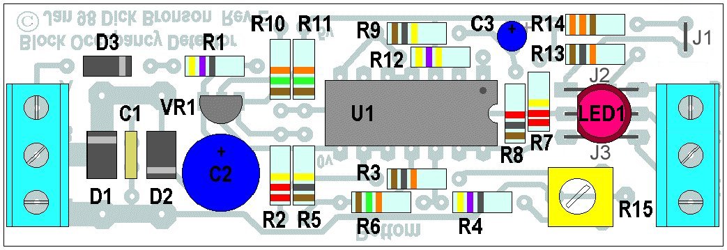
Link to Rev
G Parts Placement. (26KB) (Updated 16-Sept-98) (reference
only, no longer available)
Link to
Rev H Parts Placement. (14KB) (Updated 6-Feb-2001)
If you just want to have one or two panel indicators, or to direct drive two color signals, then you may omit the opto isolator entirely and wire directly to the indicator/s from pins 1 and 2 of the opto isolator connection. This allows us to use R14 to supply the current for our signals. These connections may be brought out to the Terminal board by adding jumpers J2 and J3. To still include a local indication along with the two color LED outputs you will need to move the on-board LED, and replace it with a jumper (J1). To see how to place the parts for this option see this image. This is the wiring we use for the simple occupancy indication used on the P&W connectors. The signal common lead is "B". The occupied output is "C" and the clear output is "E". You may wire two signal LEDs in series in order to place signals at both ends of a block. New Rev H auxiliary output options allow you to drive two different opto isolators, or a direct drive panel indicator plus an opto isolator.
Link to
Rev G Parts Placement for 2 color LED output. (102KB)
(Updated 20-Feb-2000) (reference only, no longer available)
Link to
Rev H Parts Placement for 2 color LED output. (14KB)
(Updated 6-Feb-2001)
Link to
Rev H Parts Placement for auxilary output. (14KB) (Updated
6-Feb-2001)
The Detector will also work on a standard DC layout if some power source
is connected to the power input connection. Connecting to one of the accessory
terminals on a simple power pack may suffice. Try yours and see. (I have
one old DC power pack that works like this OK, and another that does not.)
I purchased all the parts from Jameco http://www.jameco.com except the 10K pot which is from Digikey. http://www.digikey.com (For small quantities Radio Shack also has a miniature pot and terminal blocks that are the correct size as well as all the other parts.) I connect my detectors with pigtails and spade lugs, however this version of the PCB will also accept terminal blocks or an edge mounted DB-9 connector. Normally you would use a 3 position block on the track end, and a two position block at the computer end. (at E and C) The parts list now includes the terminal blocks and the PC board. You could cut down the total cost some by using pigtails, etching your own boards, and/or eliminating the pot.