Optical Occupancy Detector
RR-CirKits Revision H
Characteristics:
There are a few situations when an optical detector is better than a current
detector. This detector uses the same PC board as the Rev H current detector,
but with value changes and added jumpers. Sometimes a direct indication
of train position is desired. This could be for positioning in a hidden
storage yard, detecting when a train has cleared a grade crossing, or any
number of similar jobs. If your trains are fully equipped with conductive
wheel sets, then this may not be a big problem for you. However I would
like these circuits to be useable by a larger number of people, thus the
creation of the IR detector. At first I figured that this would require
a different PC board, but after looking at the circuit requirements I decided
that this could actually be done using the existing BOD-H board. As much
as 90% of the requirements were the same. I have two different options
shown here. Neither uses an opto isolator, because the IR version of the
BOD does not need to be connected to the DCC rails. Obviously an opto device
may be used if you desire it. The IR detector is expected to be an IR sensitive
photo transistor but if you have a stable level of room lighting you may
substitute a common Cadmium-Sulfide cell and use it to detect the shadow
of passing cars.This will work best if intermittent detection caused by
passing spaces between cars is not any problem. Power can be from any convienient
12VAC or 12VDC source. The power source must have a common ground with
the controlled circuits if you chose the option without any opto isolation.
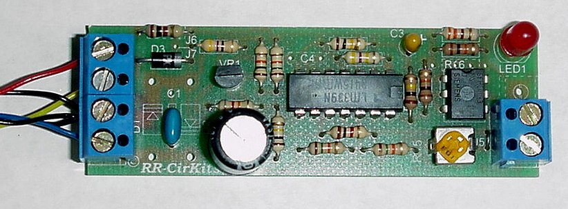
Link to picture
of IR Detector. (76KB) (Updated 6-Feb-01)
U1-B is not actually used, but it does no harm to leave it in the circuit.
The availability of track power at all times allows you to choose to power
the sensor circuitry from the DCC track power itself. You can also use
a wall wart, or a 10-12V power bus. The current drain of this circuit is
low (about 20 ma. including the power for the IR emitter), so the power
drain on a booster is not large.
Operating principles:
Link to Schematic-ir-H
(19KB) (Updated 28-Jan-01)
The simplest way to get the same voltages on the input of U1-A that
are found in the current detector version is to change the value of R2
to serve as a pull up resistor. When light shines on the input sensor it
conducts, pulling the voltage from R2 down to ground, and turning off U1-A.
C1 acts to cancel out the effects of florecent light flicker, and improves
the stability of the circuit.
D3, C2, and the 5 volt regulator VR1 provide DC power for the circuit,
and may be omitted and replaced by a jumper at J6 if you have a 5V power
source such as the crossing gate controller. R1 is to limit the peak charging
current of the power circuit and also acts as a fuse if the circuit fails.
R2, R3, and R15 act as an input voltage divider and biasing circuit.
R4 is to limit the current in R15 if it is adjusted to it's minimum position.
R5 and R6 generate a positive reference voltage, and power bus 'B' serves
as the zero reference point. R15 controls the amount of current required
to reach the reference voltage points. The circuit is designed to respond
in the range of 20-30K ohm equivilant resistance.
C3, R7, R8, and R9 are the timing circuit. The timing may be varied
by changing the value of C3. A value of 1.5Mfd allows for a rapid response.
U1-C drives the output stage. U1-D provides an inverted output option.
R10 and R11 provide a bias point for the driver, while R12 and R13 provide
the hysteresis necessary for stable switching action. R14 is the current
limiter for LED 1 and the opto isolator. If you need to drive more current
in the output of the isolator you may vary the value of R14. I use 4N28
isolators because they are the least expensive, but many different opto
isolators will serve as well depending on your needs. If you are using
simple open collector switching into a logic board like I am, be sure to
check that your isolator has enough gain to drive the pull-up resisters
used on your board. R-16 is an optional current limiter for driving one
or two external LED's.
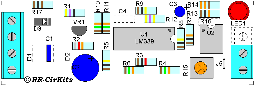
Link to Parts
Placement for optical detector. (14KB) (Updated 17-Jan-01)
If you just want to have one or two panel indicators,
or to direct drive two color signals, then you may omit the opto isolator
entirely and wire directly to the indicator/s or signals from pins 1 and
2 of the op amps. This allows us to use R16 to supply the current for our
signals. These connections may be brought out to the Terminal board by
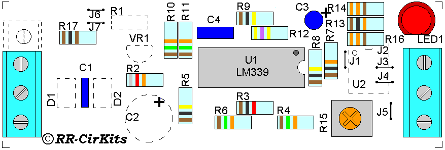
adding jumpers J1, J3 and J4. To see how to place the parts for this option
see this image. This is the wiring we use for the simple occupancy indication
used on the P&W connectors. The signal common lead is "B". The occupied
output is "C" and the clear output is "E". You may wire two signal LEDs
in series in order to place signals at both ends of a block.
Link to Parts Placement for 2 color LED output. (102KB)
(Updated 9-Jan-2001)
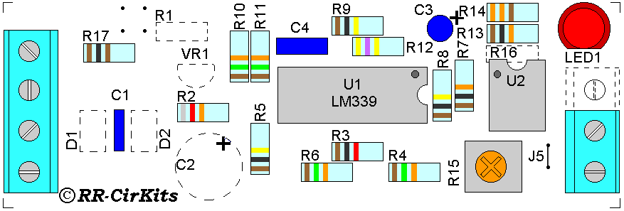
Parts Placement
for IR detector with no internal power supply. (13KB)
(Updated 17-Jan-2001)
Parts
Placement for IR detector with no internal power supply, direct LED output.(13KB)
(Updated 17-Jan-2001)
Installation:
Optical detection can be somewhat of a black art as any of you that have
tried it already know. There are a few things to remember that will help
you make a reliable system. First you need a stable source of radiation.
Room lights can be used only if you never do any night running. Also daylight
shining on the detector will cause severe problems. I find that the best
way to deal with this is to shield the detectors from both room lighting
and daylight. Then provide your own source of radiation. This can be an
IR emitter diode if you are using a IR sensitive detector, or a lamp if
you are using a cadmium-sulfide detector. Either build a hood for the detector,
or paint all sides except the lense itself with silver or black to block
radiation coming from any direction except your emitter. Position the emitter
and detector at the same height as the couplers, and slightly offset. This
will reduce the chances of light sneaking between cars and providing a
false clear. A nice hood can be built from a short piece of .078 OD (5/64")
brass tubing press fit into the lense recess on the front of the detector.
A touch of flat black on the inside will improve the shielding effect.This
keeps stray light from hitting the lense. If you are using the detectors
for train position sensing in a hidden yard, then you may find it easy
to have the light emitter mounted above the trains and the detector in
the middle of the tracks, as they will be less subject to knocking about
when mounted that way..
Parts List for Optical Detector:
Parts List:
Ref. Qty Part
------------------------
C1 1 .1/25
C2 1 220/25
C3 1 1.5/25
D3 1 1N4001
LED1 1 LED
R1 1 1/4W
47
R2 1 1/4W
82K
R3
1 1/4W 1K
R4,6,10,11 4 1/4W 15K
R5,8,9 3 1/4W 100K
R7,13 2 1/4W 10K
R12 1 1/4W 470K
R14,16 1 1/4W 330
R15 1 10K Pot
R17 1 1/4W 100
U1 1 LM339
U2 1 4N28
VR1 1 78L05
detector 1 MTS-461 (black back)
emitter 1 MES-760 (white back)
1 2/3-Term
1 3/4-Term
BOD-H 1 PC
Board
Last updated 6-Feb-2001