PIA-8255 Introduction
The Tanner Soft PIA8255
WinLok driver is a System Based Driver for 8255 compatible parallel
I/O cards. It is NOT the same as the original Parallel Sensor software
that is built into the WinLok program to drive the same cards. The inputs
from this new driver map into the same serial I/O space as other system
based inputs such as the Digitrax DS-54, Märklin s88, Lenz LR-100
etc., and the outputs are controlled by the same Switch/Signal Solenoid
Device commands that are used for other output devices such as stationary
decoders.
This new driver enables modelers that do not have DCC, or who's DCC
system does not support the commonly available DCC input or output devices
to still have the advantages of using WinLok for layout control, and/or
to be able to develop a fully computer based CTC system. Using the WinLok
MultiDrive driver module allows for full integration of both serial
input devices and parallel I/O based devices into one seamless system.
The user can easily use a digital I/O card for occupancy detection and
signal operation, with the track switch position and feedback information
being taken care of with a DS-54 or similar stationary decoder.
PIA-8255 Driver installation
1. If you have not already done so, setup the hardware of your Digital
I/O card to a single unused I/O space on your PC. You may need to make
a list of all the Input/Output ranges used on your machine to find a suitable
setting. You can accomplish this by going into the Control Panel - System
Properties - Device Manager. Open up each device in turn and look under
the Resources tab for the Setting of the Input/Output Range. Record the
range used by each device. Note, some devices will not have a resources
tab, and some may not have any entry for the Input/Output Range. Just ignore
these entries, as they will not be using any conflicting resources. Once
you have identified all the system I/O space already in use by your machine,
you can easily select a range to be used by your new I/O card. This will
require that you locate a free space of at least 4 bytes per 8255 port.
Each 8255 port supports 24 bits. (i.e. the 144 bit ACL-7122 will require
24 bytes of unused I/O space) The default setting of 2C0H will work for
many systems. The PIA-8255 driver does not need to use an interrupt, so
you should disable the interrupt setting of your 8255 I/O board.
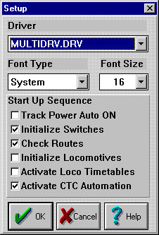 2.
If you are using more than just the PIA8255 driver as we are in this example,
then first you will need to install the MultiDrive driver. Go to General
- General Setup and enter MULTIDRV.DRV as the Driver. Check any of the
Start Up Sequences you may desire, and then click OK. 2.
If you are using more than just the PIA8255 driver as we are in this example,
then first you will need to install the MultiDrive driver. Go to General
- General Setup and enter MULTIDRV.DRV as the Driver. Check any of the
Start Up Sequences you may desire, and then click OK. |
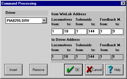 Now
go to the MultiDrive drop down entry on the toolbar and click on Driver
Assignment. Choose Insert to add each driver that you will need. Select
each driver in turn and choose which WinLok addresses will be used by that
driver. In this example we will reserve the first 18 Locomotives, the first
144 Solenoid devices and the first 9 banks of Feedback Modules for the
PIA8255 driver. Now
go to the MultiDrive drop down entry on the toolbar and click on Driver
Assignment. Choose Insert to add each driver that you will need. Select
each driver in turn and choose which WinLok addresses will be used by that
driver. In this example we will reserve the first 18 Locomotives, the first
144 Solenoid devices and the first 9 banks of Feedback Modules for the
PIA8255 driver. |
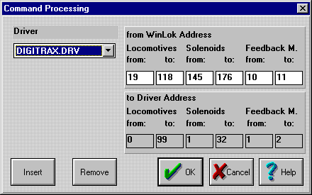 Next
we will reserve 100 Locomotives (19-118) 32 Solenoids, and 2 banks of Feedback
Modules for our Digitrax driver. Next
we will reserve 100 Locomotives (19-118) 32 Solenoids, and 2 banks of Feedback
Modules for our Digitrax driver. |
 3.
As mentioned above in the introduction, the new PIA-8255 driver no longer
uses the original internal WinLok parallel software. Instead it interacts
with the system exactly the same as a set of serial system feedback sensors.
To install the 144 port ACL-7122
you will need to define at least 9 System Based Serial 16 Input Feedback
Modules. (The Märklin s88 sensors are used as the default type.) In
our setup example we will also be installing some Digitrax DS-54 modules,
so setup for at least 10 feedback sensor modules. (9 for the ACL-7122,
and 1 for the DS-54) To do this, go into the Database drop down list and
select Feedbacksensors. Select Serial, and then enter the total number
of 16 input feedback module groups that you will need. Check the "Use Feedbackmodules"
check box if you want the system to check the status of the sensors as
soon as track power is turned on.
4. Next we need to choose what sections of the ACL-7122
will be used for input devices, and which sections will be reserved for
output. Use the accompanying worksheets to determine these assignments.
(ACL-7122 Input worksheet
- ACL-7122 Output
worksheet) Note that any circuit ID (port and byte) may only be used
once. If for example you choose to use section 1A for input, then you should
scratch through section 1A on your Output assignment worksheet. In a like
manner, if a section is used for output, then you should scratch it from
your Input assignment sheet. The assignment addresses are fixed by the
driver logic, so you may change any Circuit ID from Input to Output without
affecting any of the other assignments on the board. In other words, if
you assign 1A as an input, then ser(1,1) - ser(1,8) will become active
as inputs, but SWI(1) - SWI(8) will not exist. If later you decide to reassign
section 1A as an output device, then ser(1,1) - ser(1,8) will become inactive
as inputs, but SWI(1) - SWI(8) will become available as outputs.
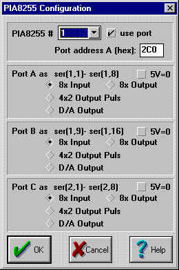  5.
Once your assignments are completed, go to the PIA8255 driver setup. Set
the port address A for the first section (#1) to the primary hardware address
that you used in your hardware setup. (E.g. 2C0) Check the "use port" check
box. Next check the radio buttons for each of the three ports A-C to select
the mode and polarity of each. setting up the desired modes for each port.
Proceed through each of the 6 sections setting each with an address that
is 4 higher than the previous one, (e.g. 2C0, 2C4, 2C8, 2CC, 2D0, 2D4)
and choosing the required modes for each one. Be sure to download
the latest version of the PIA8255 driver here as the original driver
had a minor bug that affected this step. 5.
Once your assignments are completed, go to the PIA8255 driver setup. Set
the port address A for the first section (#1) to the primary hardware address
that you used in your hardware setup. (E.g. 2C0) Check the "use port" check
box. Next check the radio buttons for each of the three ports A-C to select
the mode and polarity of each. setting up the desired modes for each port.
Proceed through each of the 6 sections setting each with an address that
is 4 higher than the previous one, (e.g. 2C0, 2C4, 2C8, 2CC, 2D0, 2D4)
and choosing the required modes for each one. Be sure to download
the latest version of the PIA8255 driver here as the original driver
had a minor bug that affected this step. |
 6.
Once you have setup your ACL-7122
or other PIA-8255 device you must enter a new item into the database to
use it for outputs. I recommend that you enter the Article Number as "PIO"
or "PIA". The Item Name is "8255 I/O Board". An example for Manufacturer
is "NuDAK ACL-7122". Define the category as "Switch". 6.
Once you have setup your ACL-7122
or other PIA-8255 device you must enter a new item into the database to
use it for outputs. I recommend that you enter the Article Number as "PIO"
or "PIA". The Item Name is "8255 I/O Board". An example for Manufacturer
is "NuDAK ACL-7122". Define the category as "Switch". |
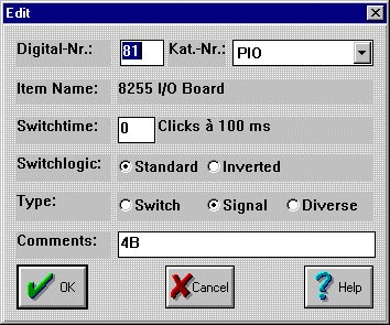 7.
Next go to the Switches and Signals database and make an entry for each
SWI output that you have defined on your worksheet as being required. The
"Digital-Nr" will be the same SWI() number shown on your worksheet. The
"Kat.-Nr" will be the name that you just entered in step #6. You may also
add a comment for each entry. For a comment I just note the Circuit ID
for each group. You will find the Copy command is very useful for this
operation due to the large number of entries to be made. 7.
Next go to the Switches and Signals database and make an entry for each
SWI output that you have defined on your worksheet as being required. The
"Digital-Nr" will be the same SWI() number shown on your worksheet. The
"Kat.-Nr" will be the name that you just entered in step #6. You may also
add a comment for each entry. For a comment I just note the Circuit ID
for each group. You will find the Copy command is very useful for this
operation due to the large number of entries to be made. |
Once all of the above steps are taken, you may start actually using
your new digital I/O device to input from or output data to your layout
using WinLok SWI() or ser() commands.
Last updated 1-26-2000
 2.
If you are using more than just the PIA8255 driver as we are in this example,
then first you will need to install the MultiDrive driver. Go to General
- General Setup and enter MULTIDRV.DRV as the Driver. Check any of the
Start Up Sequences you may desire, and then click OK.
 Now
go to the MultiDrive drop down entry on the toolbar and click on Driver
Assignment. Choose Insert to add each driver that you will need. Select
each driver in turn and choose which WinLok addresses will be used by that
driver. In this example we will reserve the first 18 Locomotives, the first
144 Solenoid devices and the first 9 banks of Feedback Modules for the
PIA8255 driver.
 Next
we will reserve 100 Locomotives (19-118) 32 Solenoids, and 2 banks of Feedback
Modules for our Digitrax driver.
 3.
As mentioned above in the introduction, the new PIA-8255 driver no longer
uses the original internal WinLok parallel software. Instead it interacts
with the system exactly the same as a set of serial system feedback sensors.
To install the 144 port
 5.
Once your assignments are completed, go to the PIA8255 driver setup. Set
the port address A for the first section (#1) to the primary hardware address
that you used in your hardware setup. (E.g. 2C0) Check the "use port" check
box. Next check the radio buttons for each of the three ports A-C to select
the mode and polarity of each. setting up the desired modes for each port.
Proceed through each of the 6 sections setting each with an address that
is 4 higher than the previous one, (e.g. 2C0, 2C4, 2C8, 2CC, 2D0, 2D4)
and choosing the required modes for each one. Be sure to
  6.
Once you have setup your
  7.
Next go to the Switches and Signals database and make an entry for each
SWI output that you have defined on your worksheet as being required. The
"Digital-Nr" will be the same SWI() number shown on your worksheet. The
"Kat.-Nr" will be the name that you just entered in step #6. You may also
add a comment for each entry. For a comment I just note the Circuit ID
for each group. You will find the Copy command is very useful for this
operation due to the large number of entries to be made.