The LocoBuffer II is currently the most reliable way to connect a computer to a LocoNet®. This Ready To Run commercial unit is produced by RR-CirKits, and based in part on the original LocoBuffer design.
Note: For those that want to build up their own LocoBuffer you may get parts and boards from Hans deLoof.
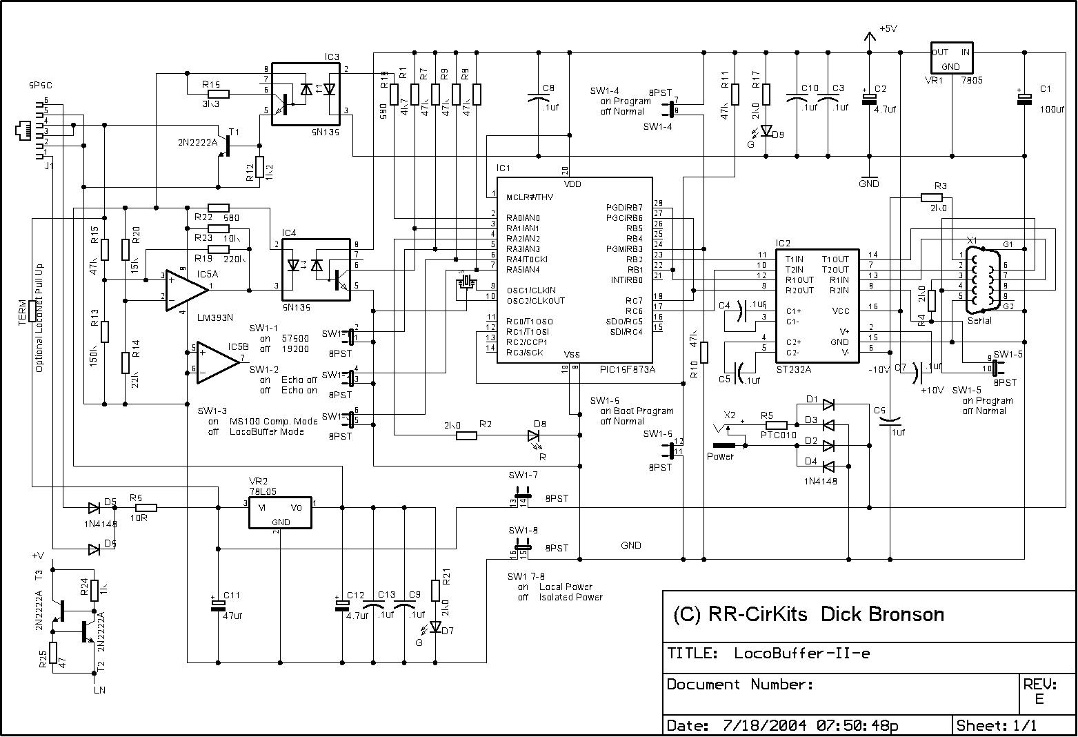
Schematic notes: This new schematic is for the revised version of the LocoBuffer-II. These revisions include extensive internal changes to convert it to SMT technology, but no functional changes of importance to the user. We originally considered calling this a LocoBuffer-III due to the large number of changes, but decided that functionally it was still a LocoBuffer-II, and that shall remain it's name.

Laptop with Serial Port - LocoBuffer-II
Desktop with Serial Port - LocoBuffer-II-P
Laptop or Desktop with USB only - LocoBuffer-II-P-USB
Mac with DIN-8 - LocoBuffer-II-P-Mac
Mac with USB only - LocoBuffer-II-P-USB
The recommended basic setup for the LocoBuffer II is:
To perform a very basic LocoBuffer-II sanity test do the following.
Steps:
Explanation of the above is as follows. Unplugging the LocoNet® cable removes the termination. Power up with Sw 7-8 closed powers both sides of the unit which lights both green LED's. The processor boots up and after a short (barely noticeable) delay starts monitoring the status of the LocoNet®. With no termination the LocoNet® looks like it is "busy" so the processor lights the red activity light. When the LocoNet® cable is plugged in it sees the command station and it no longer appears that the LocoNet® is "busy", so the activity LED is extinguished. This simple test shows that the LocoBuffer-II power circuits are OK, that it can read the LocoNet® status, and that the processor is running. It does not test any of the serial port connections, nor the capability to send commands to the LocoNet®. Note: If there is a noticeable delay of about 1 second before the LED lights, then the LocoBuffer-II boot loader code may be missing. This will not be a problem unless you need to upgrade the firmware. (currently there are no upgrades to the firmware)
If the activity LED does not extinguish when you plug in the LocoNet® cable, be sure that your DCC command station is powered up, then check your LocoNet® wiring. To further test the LocoBuffer-II do the following Loop Back Test.
The LocoBuffer-II input circuit and code actually reads from the LocoNet® output jack, so if you install the LocoNet® terminator (the small circuit that is shipped with the LocoBuffer II) and set SW7-8 to ON (down) so that the LocoNet® circuitry gets it's power from the wall wart, then you have created a loop back test. The only thing that is not tested is the LocoNet® jack itself.
Steps:
LocoBuffer-II hex code download (1.632)
LocoBuffer-II boot loader code download
LocoBuffer-II Parts list
LocoBuffer-II Schematic
LocoBuffer-II Parts Layout
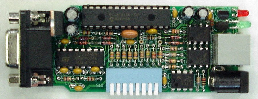
Image of production unit without it's case
Macintosh serial cable wiring
MS-Windows XP wiring concerns.
MS-Windows XP users must be sure that the cable and adapters they use include wiring for the DTR and DSR lines as well as the RTS and CTS lines. Failure to check this can cause failure of the connection on MS-Windows XP machines. If you are using an older DB-25 cable or connection plus an adapter to 9 pins, be especially sure that the adapter includes all the lines. Some that were originally included with serial mice do not.