|
Projects Semaphore Rebuild Info DCC Block Occupancy Infrared detectors DCC Controlled Coupler Little Mountain & Possum Hollow RR Mike Weber's CTC panel (June 2, '06) Other
Places Policies
Associate Links to
recommended products |


2026 NMRA LCC Information Sheet.
NMRA PSR Clinic - Arizona Railroad Historical Society Experience with LCC.
Link to Original NMRA LCC Demo Layout

RR-CirKits is one of your best sources for NMRA LCC compliant products.
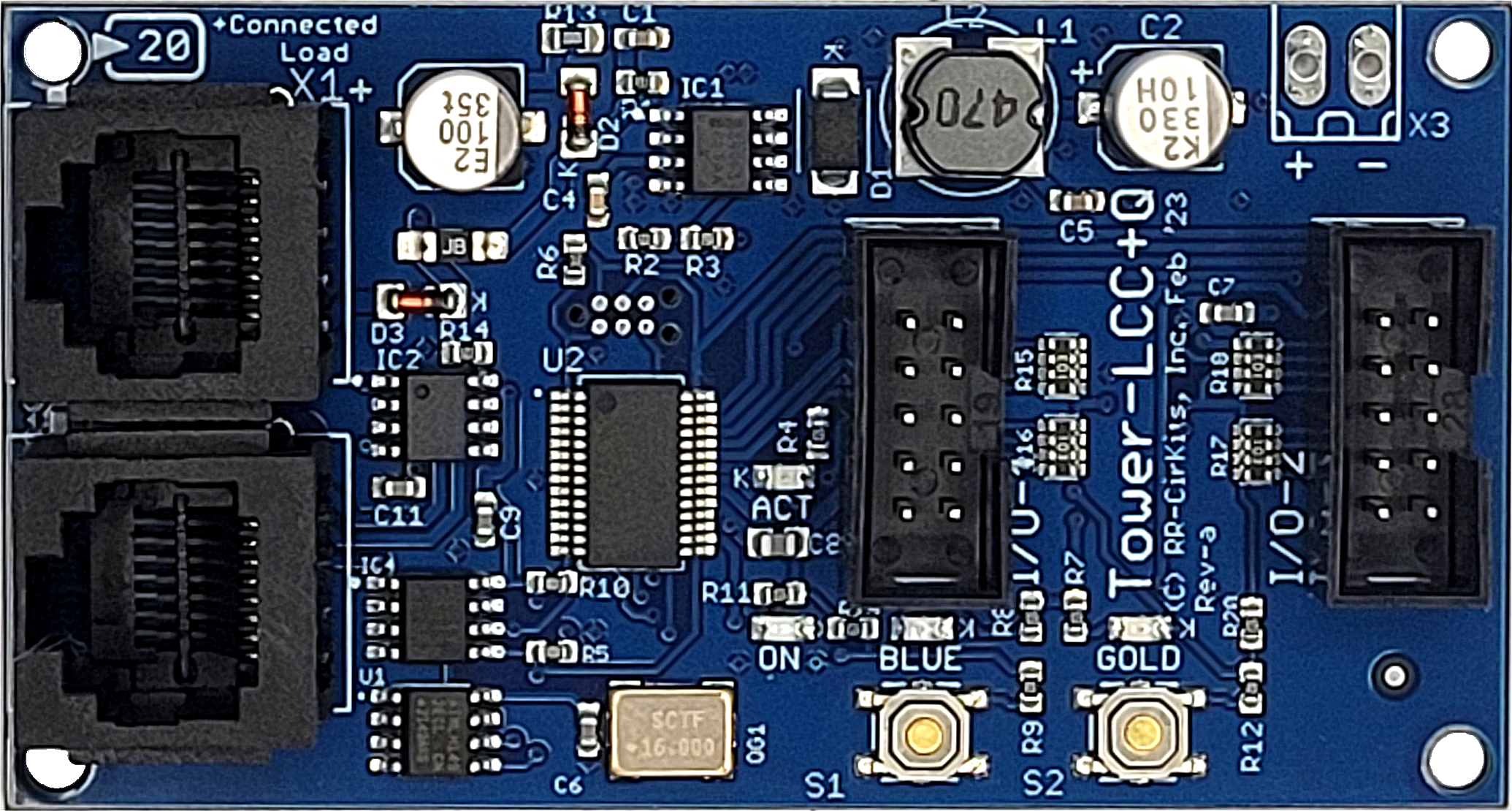
Tower
LCC +Q
- Tower LCC image
- Support for 16 Input/Output lines.
- Includes drive for any combination of:
- Up to 16 Input Lines.
- Up to 16 Output Lines.
- New Internal Logic Engine with 4032 characters of logic statements.
- Communicates over the CAN bus version of LCC.
- CDI controlled configuration via Software. (e.g. JMRI DecoderPro 5.6 or later.) Both reading and writing of description values is directly supported.
- All configuration is stored internally in the nodes, and may be changed at any time on any system. (no local files to keep up to date)
- Automatically saves all data including input/output states during power down.
- Boot Loader protocol allows firmware upgrades over the LCC Bus connection.
- Power is supplied over the LCC Bus.
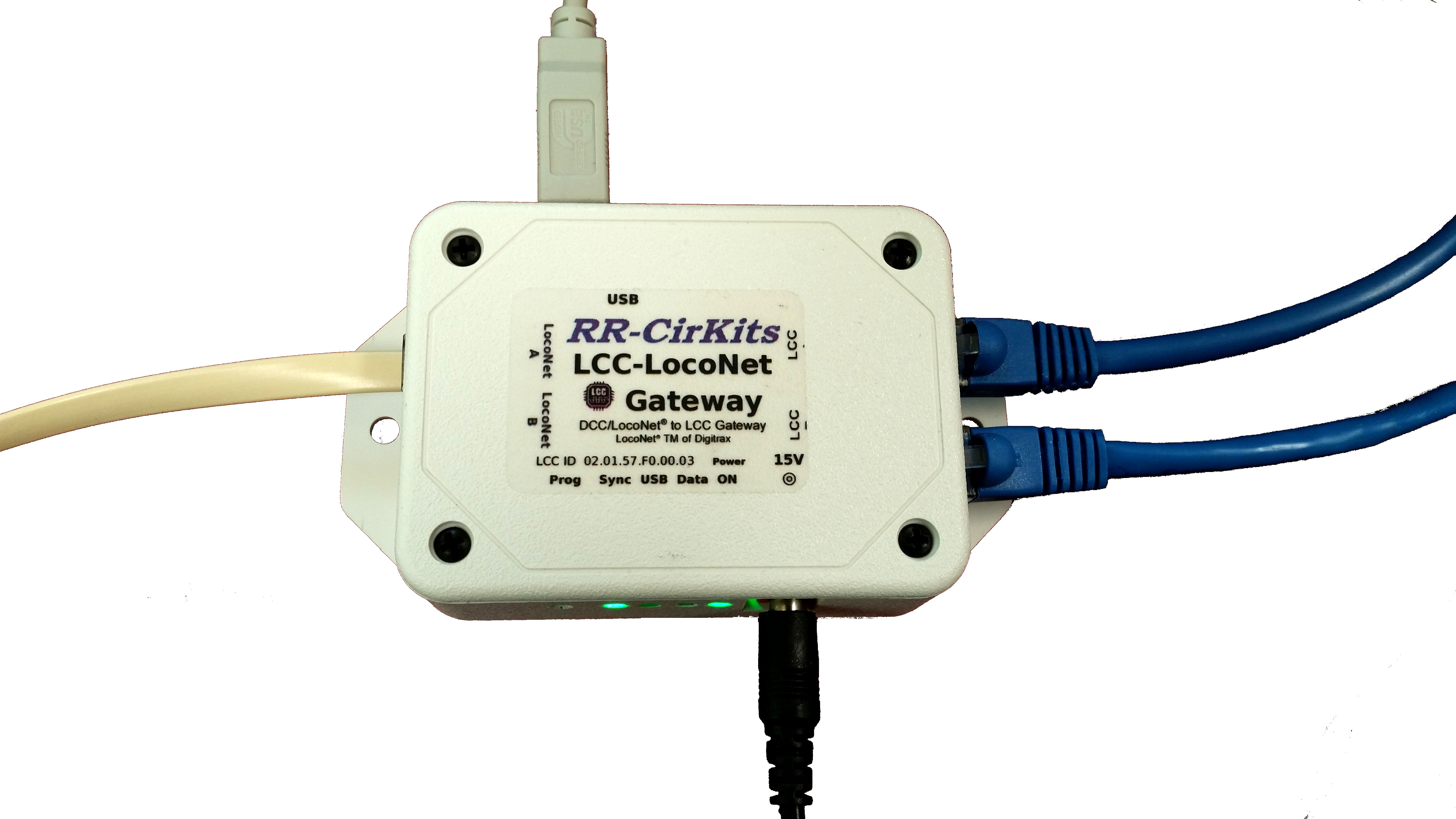
LCC-LocoNet
Gateway
- LCC-LocoNet Gateway image
- Manual
- Add LCC nodes to an existing LocoNet layout.
- Add LocoNet devices to an LCC controlled layout, including LocoNet throttles to Traction Control Protocol.
- Supports up to 1024 arbitrary Input/Output conversion pairs.
- Supports LCC 'Well Known Events' for accessory commands and sensor inputs to LocoNet LT & LS messages.
- Includes an internal NMRA CAN bus LCC® to USB interface. (no external LCC Buffer-USB required)
- 2,500 Volt High Speed Digital isolation between LCC® CAN bus, LocoNet®, and USB port.
- USB Type C connector for PC connection.
- Dual RJ45 connectors for easy CAN bus LCC® loop through connections.
- Dual RJ12 LocoNet connectors for easy LocoNet® loop through connections.
- 4 LED display status. (Sync, USB, Data, and On)
- Small package size. Just 2-7/16" x 3-5/16" x 1-1/8".
- Ready to run unit includes USB cable, LocoNet cable, LCC Terminators, and 15V power supply. Nothing extra to purchase.
- Standard 125,000 Baud CAN bus LCC interface speed. No jumpers or switches to set.
- Buffered inputs and outputs for full speed, error free data transmission.
- Powered directly from LCC® bus connections* and USB port, or else create a powered LCC bus using the unit and power supply.
- Includes optional stand alone LocoNet circuitry.
*Note: Requires a powered LCC bus. [50 mA. bus load]
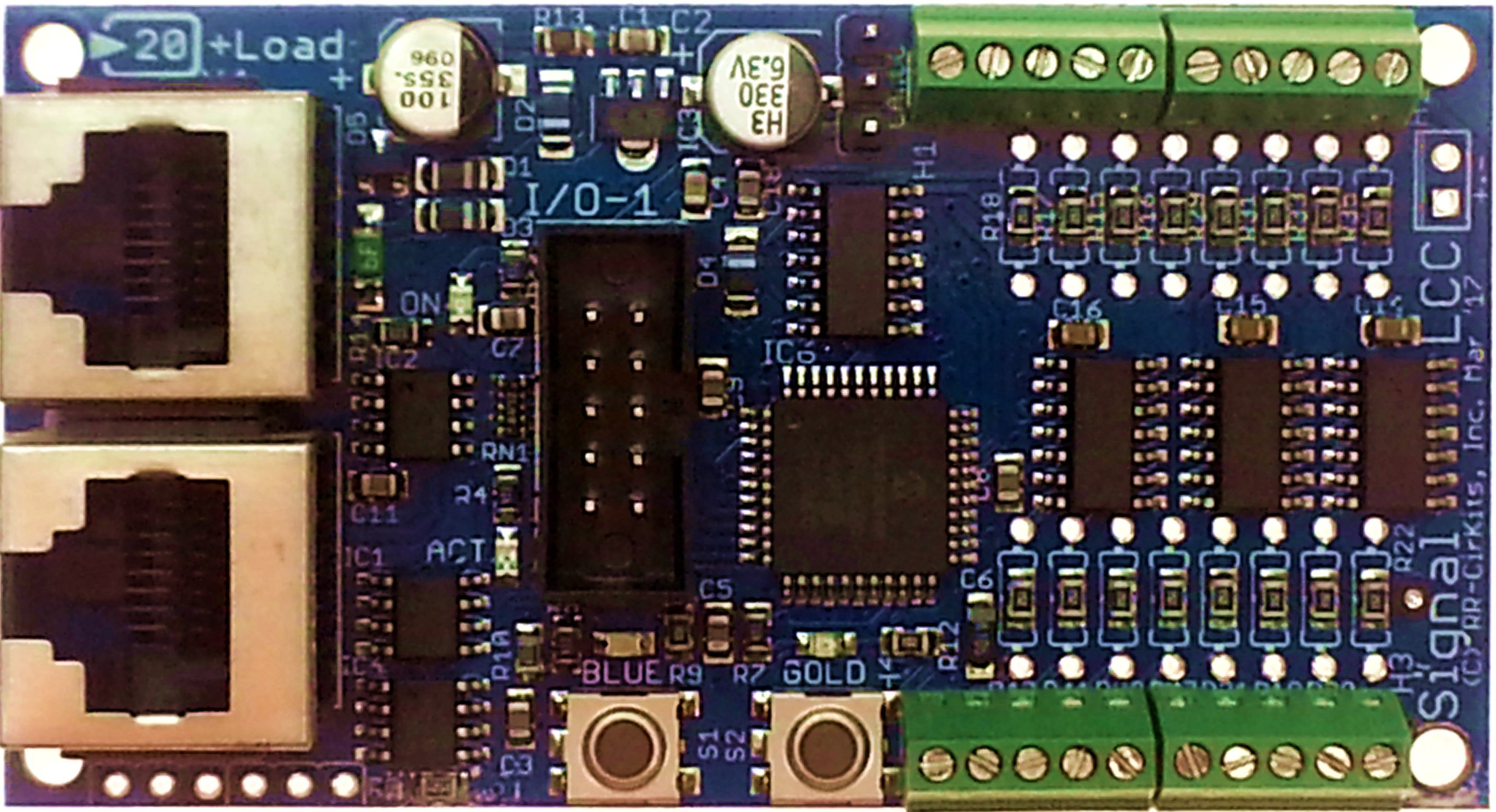
Signal LCC
- Signal LCC image
- Support for 16 signal lamps plus 8 I/O lines.
- Each signal mast may use as many lamps as required.
- Available with signal connections using miniature screw terminals (-S) or 10 pin headers. (-P)
- Support for 8 Input/Output lines.
- I/O lines includes drive for any combination
of:
- Up to 8 Input Lines.
- Up to 8 Output Lines.
- Internal Logic Blocks with up to 32 conditional statements.
- Up to 8 virtual track circuits for easy linking to other signal masts.
- Communicates over the CAN bus version of LCC.
- CDI controlled configuration via Software. (e.g. JMRI DecoderPro 4.8 or later.) Both reading and writing of description values is directly supported.
- All configuration is stored internally in the nodes, and may be changed at any time on any system. (no local files to keep up to date)
- Automatically saves all data including input/output states during power down.
- Boot Loader protocol allows firmware upgrades over the LCC Bus connection.
- Power is supplied over the LCC Bus.
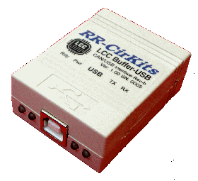
LCC Buffer-USB
- LCC Buffer-USB image
- NMRA CAN bus LCC® to USB interface.
- 2,500 Volt High Speed Digital isolation between CAN bus LCC® and USB port.
- Simplify your LCC configuration and/or use a PC based CTC.
- Compatible with JMRI OpenLCB.
- Type B USB connector for PC connection.
- Dual RJ45 connectors for easy CAN bus LCC® loop through connections.
- 4 LED display status. (Ready, Power, Transmit, and Receive)
- Small package size. Just 1-1/2" x 2-1/4" x ¾".
- Ready to run unit includes USB cable. Nothing extra to purchase.
- Standard 125,000 Baud CAN bus LCC interface speed. No jumpers or switches to set.
- Buffered inputs and outputs for full speed, error free data transmission.
- Powered directly from LCC® bus connections* and USB port.
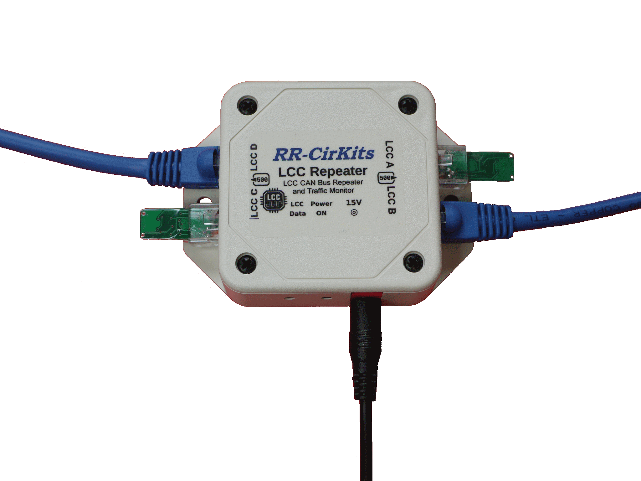
LCC Repeater
- LCC Repeater image
- Bit level repeater connects two LCC ® CAN bus segments.
- Quad RJ45 connectors for dual LCC ® CAN bus loop through connections.
- Includes a CAN bus data monitor LED for network trouble shooting. 2 LED display.
- Small package size. Just 2-1/2" x 3-1/2" x 1". (including mounting flanges)
- 600 ma power supplied to each LCC ® CAN bus segment.
- 15VDC 1.2 Amp Universal Switching Power Supply included.
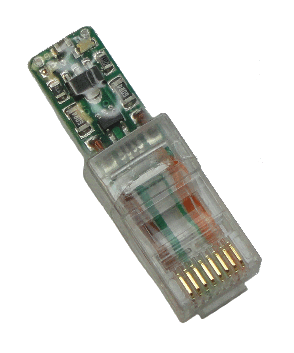
LCC Terminator Pair
- LCC Terminator image
- NMRA CAN bus LCC® Termination Pair.
- May be used to provide the required termination at each end of the CAN bus LCC®
- Balanced CAN termination provides the best noise rejection.
- Includes
CAN bus Power Indicator and CAN bus data monitor for
easy network cable trouble shooting.
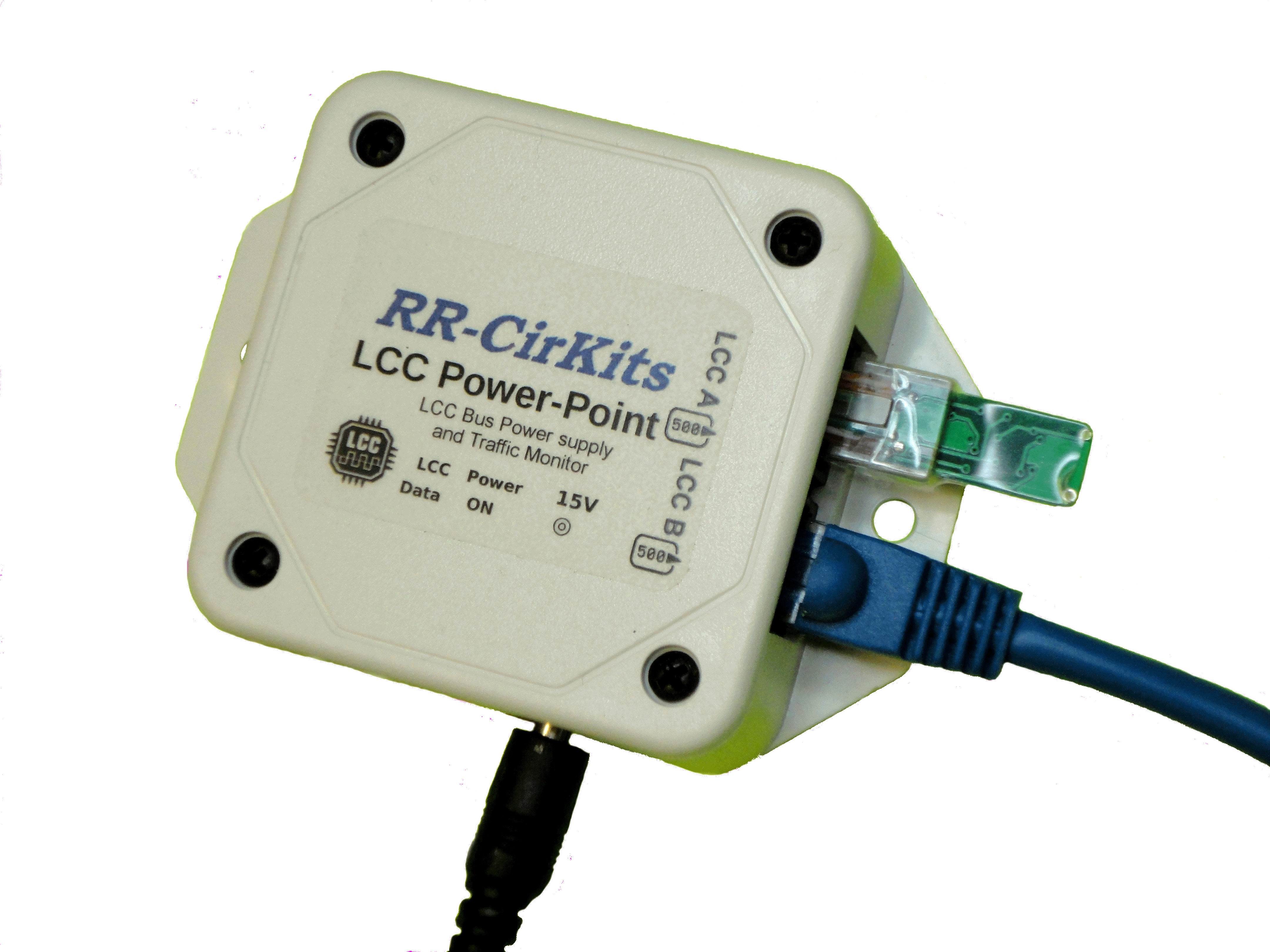
LCC Power-Point
- LCC Power-Point Image
- LCC Power-Point ties together 2 LCC jacks, a Traffic Monitor, and a power supply.
- Create a powered LCC bus for simple wiring by powering your LCC Nodes over the cable.
- The LCC Power-Point supplies 1/2A to each LCC CAN Bus cable.
- PS-S-15-1200 universal switching power supply is included. (Terminator and CAN bus cable shown are not included)
- Additional Power-Point units may be added as required by your system's power requirements.
LCC® is a trademark of the NMRA
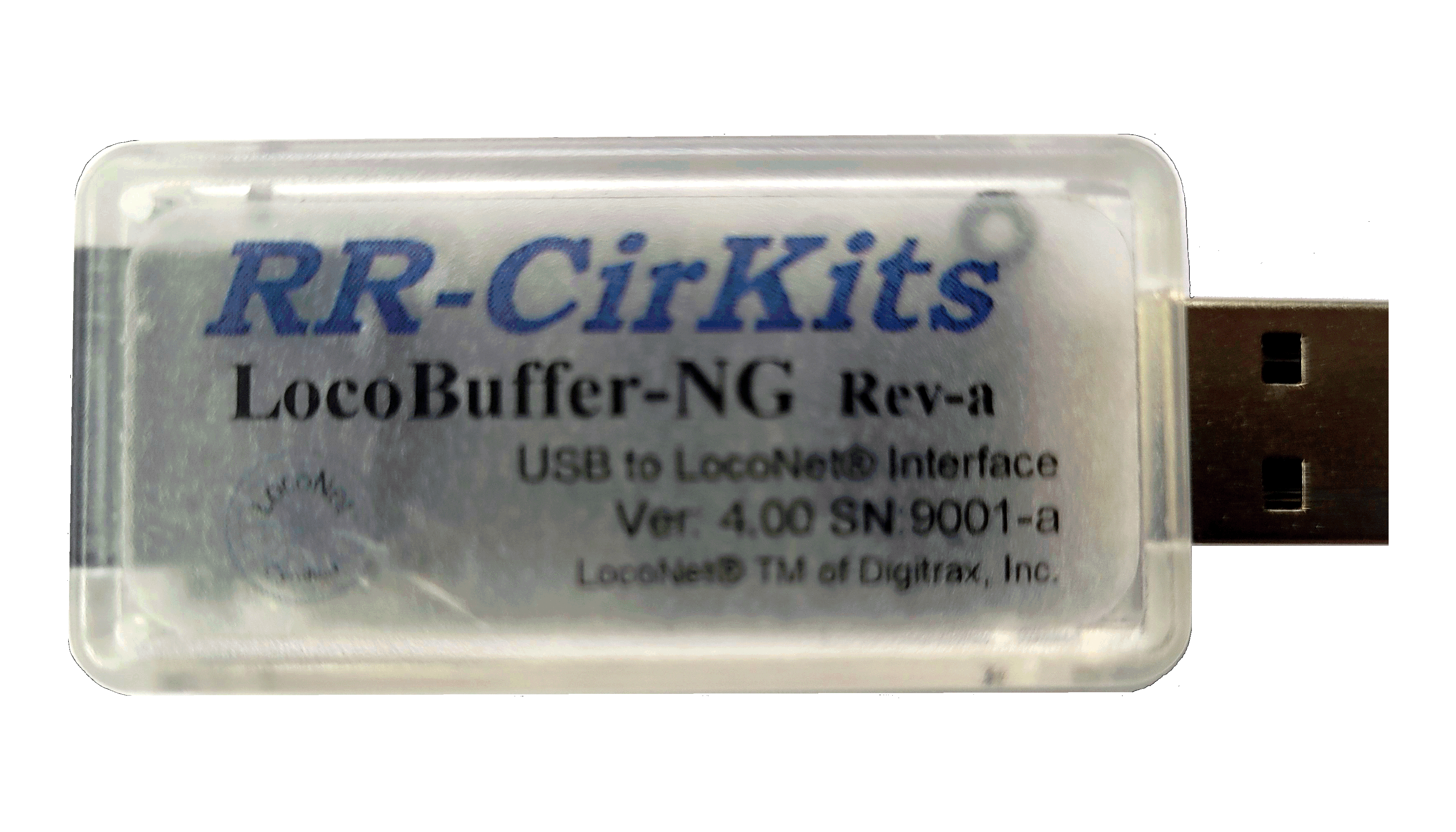
LocoBuffer-NG
- Next Generation USB to
LocoNet® interface with type A USB
connector.
- Plug and play for Linux, Mac, Windows 10 & 11.
- 2,500 Volt Digital isolation between USB and LocoNet®
- Keep your system up and running through ground loops, spikes, and surges. Rogue currents and ground issues can wreak havoc with your data, and even damage your LocoNet.
- Buffered inputs and outputs allow use with all operating systems with USB support.
- More robust output design, reduced sensitivity to wiring errors.
- Even smaller (dongle style) package size. Now just 2" x 1" x 5/8"
Digital Isolation: Your best investment Keep your system up
and running. Prevent ground loops, spikes, and surges.
Windows 11 does NOT support
LocoBuffer-USB Drivers. Use LocoBuffer-NG
Windows 10 Install Instructions for LocoBuffer-USB Drivers
LocoBuffer-USB drivers (Driver download is not required for LocoBuffer-NG)
Now includes beta drivers for Mac Big Sur.